Artifacts and Models
Artifacts are elements that represent aspects of the solution and the environment in which it operates or will operate. Artifacts can describe the capabilities of the solution (such as Requirements and Use Cases), solution designs (for example, Screens, Services, and Tables), or aspects of the problem domain (Processes, Business Rules, Domain Terms, etc.). Artifacts are analyzed and modeled during the analysis and design phases. They serve as input for development, and some are subsequently transformed into living documentation after the solution is released.
Establishing a set of predefined artifacts enables teams to standardize their analysis and design outputs across projects. This improves the readability of materials and simplifies the onboarding of new team members. Because artifact types and the way they are specified and structured are unified, switching between projects is seamless because the artifacts look very similar. Each artifact is essentially an object with a defined type, identifier, attributes, and relationships to other objects. This drastically improves the reuse of artifacts across multiple places; thanks to unique identifiers, they can be referenced precisely. Furthermore, continuously building these relationships enables the tracking of dependencies between artifacts, which is crucial for detecting the downstream impacts of future changes.
Standard artifacts are highly beneficial during the analysis phase to unify outputs, but they are equally crucial for documenting already released solutions so that all solution specifications look consistent and conform to the same rules. Having consistent documentation composed of unified artifacts greatly supports a team's ability to search for information quickly and makes switching between projects and solutions much easier.
Requirement
Requirements are not limited to simple "The system shall…" statements. They can be represented by a straightforward text statement, or by complex algorithms and models. Even a user interface screen description can be a requirement if a stakeholder provides it and requests that it be implemented exactly as shown. So, what is the relationship between a requirement and an artifact? Basically, a requirement is one type of artifact. It is an object that holds metadata describing it—such as a name, description, author, and priority—and it can link to other artifacts. On the other hand, it is very common to describe a requirement using other artifacts. For example, when a development team is supposed to implement a system interface with a specific input and output, even though that interface is a design artifact, it is also functionally a requirement.
Use Case
Use cases describe the interaction between a user and the system, usually specified in the form of a textual scenario. The scenario reads like a "ping-pong" game played between the user and the system—a user action triggers a system response:
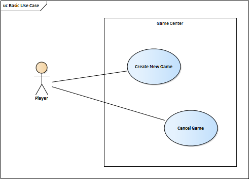
UC: Create New Game
- The user selects the option to create a new game.
- The system displays a wizard for entering game parameters.
- The user enters the game information and selects the desired map.
- If the selected map is a multiplayer map, the user selects players for the game.
- The system creates the game and sends notifications to the invited players.
- The use case ends.
The goal of use cases is not to create a detailed specification that enables the complete development of the system. Their purpose is to define the scope of the system by providing a high-level overview of what users want to do with the system, not how. Use cases outline the capabilities users expect from the system, but they omit implementation details such as user interface designs, data structures, or technical integrations.
Use cases can also be represented by a use case diagram, which depicts who (actor) performs what (use case) within which system boundary:
Activity
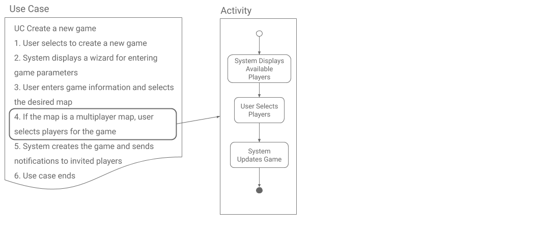
Use cases are an excellent tool for understanding how users intend to interact with a system, and a list of use cases helps establish an initial view of the system's scope. However, use cases alone are insufficient for a successful system implementation because they do not provide enough granular detail. For example, most use case steps are not atomic; to provide the necessary detail, they must be broken down into specific substeps. These substeps have their own scenarios and often resemble "mini use cases." Calling them use cases would be incorrect, though, because use case analysis has a specific architectural goal, and crowding them with low-level steps would break that focus. This is why in Effective Analysis, these detailed steps are called "activities" rather than use cases.
Activities have their own scenarios that look very similar to use case scenarios, but unlike use cases, activities can be further decomposed into more granular activities until they reach a level of detail suitable for development. It is up to the analyst to decide how deep the analysis should go and how detailed the lowest-level activities should be. As a rule, an activity is not just an isolated system function; it always involves some level of user interaction.
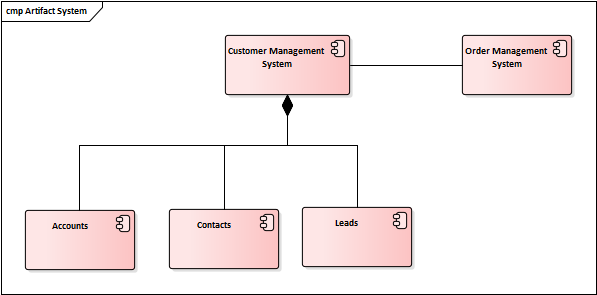
Application Component
An application component is a representation of a system or a logical system module. Components are used to describe the systems and applications an organization operates or develops, their capabilities, and the relationships among them. The benefit of maintaining a list of systems as unique objects is the ability to model relationships between them, identify dependencies, and discover the potential impacts of future changes.
Function
An application function describes the internal behavior of an application component. For example, if you need to explain how the grand total of an invoice is calculated, it can be modeled using a calculateGrandTotal() function. However, a function does not always have to be a calculation. Other examples include: saving a contact to the database, executing a long-running background job, or invoking an external service. Even though the name "function" might sound like a technical piece of code, in this context, it is not an implementation artifact—it is not a real system procedure or a method written in a programming language. Instead, it is an analytical artifact that describes a logical procedure without prescribing how it will be implemented in code.
Service
An application service exposes a component's functionality to its environment. If the Customer Management System can create a new contact and needs to allow other systems to invoke this function remotely, it will expose this capability through a createContact() service. Again, this is a purely logical artifact independent of any specific technology. It states that such functionality can be invoked on the system, but it says nothing about the underlying technical implementation—such as whether it will be delivered as a SOAP web service or a REST API.
Interface
An application interface is the logical channel through which a component's services can be accessed. For example, if the Customer Management System allows other systems to manipulate its contacts remotely, it will provide Get Client and Delete Client services, which will be logically grouped and exposed through a Contacts interface.
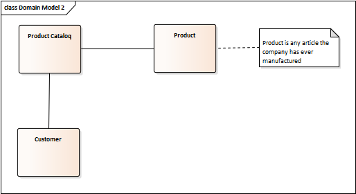
Domain Model
A domain model is a graphical representation of the most important entities forming the problem domain and the relationships between them. It is used to understand core business terms and how they relate to one another, making it an excellent tool for introducing newcomers to the business realm. It is typically modeled using a standard UML class diagram:
Activity Diagram
An activity diagram visually presents a series of actions and the flow of control within a system or a business process. Depending on the selected level of detail, it can represent low-level system behavior on one hand (such as a calculation) or a high-level business process on the other.
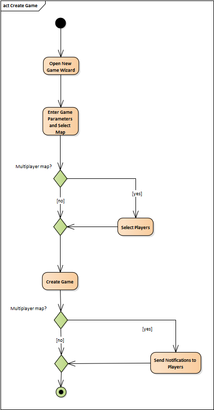
The example above models this flow:
- Open the new game wizard.
- Enter game parameters and select a map.
- If the selected map is a multiplayer map, select the players.
- Create the game.
- If the selected map is a multiplayer map, the game center notifies all invited players.
Sequence Diagram
A sequence diagram is used primarily to show interactions between objects in the exact chronological order in which they occur. Unlike activity diagrams, which also show the sequence of steps, sequence diagrams focus heavily on the interacting objects themselves. Objects send messages to one another, which always triggers a reaction. For example, a Player sends a Create Game message to the Game Center, which triggers opening the new game wizard:
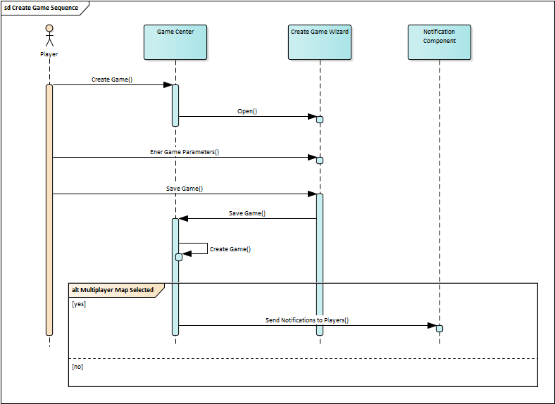
The example above models this flow:
- The player creates a game within the game center.
- The game center opens the creation wizard and displays it to the player.
- The player enters the game parameters.
- The player saves the parameters.
- The game center creates the game.
- If the selected map is a multiplayer map, the game center notifies all invited players.